Category Archives: Industry

Industry

how to construct a hockey gear drying rack

Building a hockey gear drying rack is a useful alternative to dry and air out equipment soon after use. Here’s a standard guideline on how to make a simple hockey equipment drying rack:

Elements Necessary:

– Plywood or picket boards

– 2×4 lumber

– Screws or nails

– Drill

– Saw (round noticed or jigsaw)

– Measuring tape

– Pencil or marker

– Amount

– Hooks or hangers

– Sandpaper (optional)

– Paint or stain (optional)

Directions:

1. Decide the dimension and structure: Evaluate the offered place and contemplate the quantity of equipment items you want to hold. Sketch a tough design and style or strategy the layout of the rack, like the number of shelves and hooks required.

two. Lower the materials:

– Slice the plywood or wooden boards to the desired proportions for the again panel of the rack. This will serve as the foundation for attaching the shelves and hooks.

– Lower the 2×4 lumber into lengths to construct the sides and cabinets of the rack. The dimensions will depend on your style and design and the size of your tools.

3. Assemble the body:

– Connect the 2×4 lumber vertically to the sides of the plywood or wood board utilizing screws or nails. Area them evenly to generate the aspect supports for the cabinets.

– Attach horizontal 2×4 lumber parts amongst the facet supports to develop the cabinets. The amount of shelves will rely on your layout and the quantity of equipment you want to dry.

4. Install hooks or China gear rack exporter hangers:

– Decide the placement and range of hooks or hangers wanted to cling the equipment.

– Attach the hooks or hangers to the vertical supports or shelves applying screws or nails. Be certain they are securely fixed to hold the body weight of the machines.

five. Optional: Finishing touches:

– Sand the surfaces of the rack to smooth any rough edges or splinters.

– Utilize paint or stain to the wooden for a completed appear and to shield it from dampness. Let it to dry totally prior to use.

6. Mount the rack:

– Choose on the site for the rack, guaranteeing there is ample area for the gear to hold freely and air out.

– Mount the rack to a wall or suitable area employing screws, guaranteeing it is securely hooked up and stage.

seven. Dangle the equipment:

– Hold the hockey China gear rack exporter on the hooks or hangers, letting enough spacing among merchandise to be certain proper airflow for drying.

Don’t forget to test and rotate the gear periodically to assure extensive drying. Furthermore, look at inserting the rack in a nicely-ventilated area or around a supporter to aid speedier drying.

Notice: This information supplies a basic framework for constructing a hockey equipment drying rack. You can personalize the style to in good shape your specific requires and out there place. If you’re not snug with Diy initiatives or deficiency the vital resources, take into account looking for help from a professional carpenter or handyman.
What size are injection molded pieces?

The dimension of injection molded parts can fluctuate drastically based on the distinct software, style needs, and the abilities of the China Injection molded parts distributor molding machine. Injection molding can generate elements ranging from really modest factors to huge and intricate constructions. Here’s an overview of the dimension assortment for injection molded elements:

1. Little Sections: Injection molding is normally utilized to create modest components with intricate features and specific proportions. These components can be as smaller as a number of millimeters or even more compact. Illustrations contain electronic connectors, buttons, gears, microfluidic gadgets, and little automotive components.

2. Medium-Sized Sections: Injection molding is also acceptable for developing medium-sized elements that vary from a few centimeters to a number of tens of centimeters in dimension. These elements can have extra intricate geometries and may perhaps require supplemental functions this kind of as ribs, bosses, and snap-in shape connections. Illustrations include equipment factors, clinical device housings, automotive inside pieces, and customer solution parts.

3. Massive Elements: Even though injection molding is frequently affiliated with smaller sized parts, it is also capable of generating huge pieces. Massive injection molded sections can selection from tens to hundreds of centimeters in dimensions. These areas may possibly have thicker partitions, enhanced structural necessities, and may call for specialised devices for creation. Examples involve automotive bumpers, instrument panels, huge containers, and China Injection molded parts distributor some industrial elements.

It truly is crucial to note that the measurement of injection molded elements is motivated by different elements, like the abilities of the injection molding equipment, mold style and design considerations, product flow traits, cooling time, and the mechanical homes expected for the section.

The particular dimensions limitations might range based on the tools and amenities accessible. Customized injection molding firms can give more exact information and facts on the dimensions capabilities of their equipment and molds based mostly on their certain capabilities and tools technical specs.

is cv jont failure widespread?

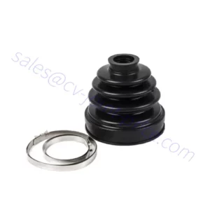
CV joint failure is not uncommon, particularly in autos with larger mileage or people subjected to harsh driving ailments. Although CV joints are developed to be durable, they are nevertheless matter to have on and tear above time. The frequency of CV joint failure can rely on a number of variables, including:

1. Driving disorders: Constant velocity joints can be far more inclined to failure in vehicles that are usually driven on tough or uneven terrain, as effectively as all those uncovered to extreme grime, gravel, or highway debris. Extreme off-highway driving, intense acceleration, and regular sharp turns can also speed up the put on on CV joints.

two. Maintenance and care: Correct maintenance and regime inspections of CV joints can help detect early signs of don or injury. Regularly checking and China cv joint exporter changing weakened CV joint boots, maintaining adequate ranges of grease, and addressing any irregular noises or China cv joint manufacturer vibrations instantly can assist lengthen the everyday living of the CV joints.

three. Excellent of parts: The high-quality of the CV joints and connected elements can impression their longevity. Applying superior-high quality, OEM (Primary Devices Company) or highly regarded aftermarket CV joints can deliver superior toughness and general performance in contrast to decrease-quality or substandard parts.

4. Driving routines: Aggressive driving practices, these kinds of as fast acceleration, hard braking, or frequent sharp turns, can set added pressure on the CV joints and raise the chance of failure.

Whilst CV joint failure is not unheard of, it is vital to notice that common inspections, upkeep, and prompt repairs can aid mitigate the risk and increase the lifespan of the CV joints. If you expertise any symptoms of a failing China cv joint manufacturer joint, it is proposed to have your car or truck inspected by a experienced mechanic to handle the situation instantly and reduce additional destruction.

what does a drive shaft do?

A push shaft, also regarded as a propeller shaft or prop shaft, is a mechanical component employed in autos to transmit torque from the motor to the wheels. It performs a essential job in transferring energy and rotational motion from the vehicle’s electric power source (engine or motor) to the wheels, enabling the car to go.

Here are the main features and tasks of a travel shaft:

1. Torque transmission: The main function of a generate shaft is to transmit torque, or rotational power, from the motor or motor to the wheels. As the motor generates electrical power, it sends rotational movement by the transmission or transfer case, China drive shaft which is then transferred to the push shaft. The drive shaft carries this rotational drive and delivers it to the differential, which further distributes the electric power to the wheels.

2. Connecting differentials and axles: In motor vehicles with rear-wheel drive, four-wheel drive, or all-wheel China drive shaft manufacturer techniques, the push shaft connects the transmission or transfer situation to the differential(s). The differential, in turn, splits the torque among the wheels, allowing them to rotate at distinct speeds during cornering although maintaining traction and security.

three. Accommodating suspension motion: The travel shaft must be developed to accommodate the movement and travel of the vehicle’s suspension method. As the wheels shift up and down thanks to bumps, uneven surfaces, or suspension articulation, the generate shaft requirements to flex or regulate its length to protect against binding or hurt. Universal joints or CV joints (Frequent Velocity joints) are normally integrated into the travel shaft to let for these actions while maintaining a steady rotational link.

four. Keeping balance: Push shafts require to be balanced properly to decrease vibrations and make certain smooth procedure. Imbalances in the drive shaft can cause unwelcome vibrations, foremost to soreness, elevated don on factors, and China drive shaft manufacturer possible drivetrain troubles. Balancing procedures, these as the addition of counterweights or precision producing procedures, are applied to reach a well balanced drive shaft.

In general, the push shaft serves as a important url in the drivetrain procedure, enabling the transfer of electricity from the engine or motor to the wheels. It performs a very important job in auto propulsion and is designed to stand up to the torque, rotational forces, and movement needed for effective and reliable operation.

What is an industrial gearbox?

An industrial gearbox factory gearbox is a mechanical machine utilised to transmit and manage electric power in many industrial purposes. It is a system of gears housed inside a protecting casing, made to cope with significant torque and provide speed reduction or enhance as necessary by the specific software. Industrial gearboxes are extensively applied in industries such as producing, mining, electric power era, transportation, and many many others.

The primary goal of an industrial gearbox is to transmit power from a key mover, this sort of as an electric powered motor or an motor, to pushed devices, these as conveyors, pumps, mixers, crushers, or other machinery. The gearbox can help match the velocity and torque qualities of the prime mover to the necessities of the driven tools. It enables for efficient electrical power transmission, velocity control, and torque multiplication or China industrial gearbox reduction.

Industrial gearboxes appear in many dimensions, layouts, and configurations to fit various purposes and operating ailments. They can be labeled into diverse types dependent on their equipment arrangements, which includes:

1. Helical Gearboxes: These gearboxes use helical gears with angled enamel to transmit ability. They supply clean operation, superior load-carrying capability, and are usually applied in applications that need precise speed regulate and very low noise amounts.

two. Spur Gearboxes: Spur gearboxes use spur gears with straight-reduce tooth. They deliver superior effectiveness and are ideal for apps that call for superior-pace power transmission and uncomplicated equipment arrangements.

three. Bevel Gearboxes: Bevel gearboxes use bevel gears to transmit electrical power between intersecting shafts. They are normally made use of in purposes that entail changing the direction of electricity transmission, these as in autos and large equipment.

4. Worm Gearboxes: Worm gearboxes use a worm equipment and a worm wheel to attain velocity reduction and higher torque multiplication. They are usually employed in apps that call for large equipment ratios and self-locking abilities, these kinds of as conveyor units and lifting machines.

Industrial gearboxes are essential factors in lots of industrial procedures, delivering responsible and productive electrical power transmission. They involve appropriate upkeep, lubrication, and periodic inspections to make sure their continued overall performance and longevity.

What aspect is a cog?

A cog ordinarily refers to a one tooth on a equipment. In the context of gears, China gear exporter a cog is just one of the specific tooth that make up the equipment system. Gears consist of various cogs or enamel that mesh alongside one another to transmit power and China gear motion.

So, to be clear, a cog is not a separate component or part distinct from a equipment. As an alternative, it is a expression that precisely refers to an individual tooth on a equipment. Gears are built up of multiple cogs, and these cogs function with each other to sort the finish gear system.

When talking about gears, it is frequent to refer to the collective arrangement of cogs or tooth on a equipment instead than focusing on unique cogs. Having said that, in particular contexts, the phrase “cog” could be utilised to describe an specific tooth or the toothed part of a China gear.

can a gearbox be repaired

Of course, a gearbox can normally be repaired dependent on the character and extent of the injury or malfunction. Gearbox repairs are generally carried out by experienced mechanics or China gearbox specialized China gearbox exporter mend stores. The restore process can contain different ways, including:

one. Diagnosis: The 1st step is to recognize the distinct challenge with the gearbox. This may involve inspecting the gearbox, conducting exams, and examining any signs or symptoms or irregular noises reported by the driver.

2. Disassembly: The gearbox is disassembled to entry the internal elements. This may well involve eradicating the gearbox from the auto and taking apart its housing and affiliated parts.

three. Ingredient Inspection: Every element, which include gears, bearings, shafts, synchros, and seals, is inspected for don, injury, or misalignment. Any faulty or worn-out components are discovered for alternative.

4. Alternative of Defective Areas: Weakened or worn elements are changed with new or reconditioned elements. It is really essential to use high-top quality substitute sections to guarantee the longevity and good functioning of the gearbox.

5. Reassembly: The gearbox is reassembled with the changed or China gearbox exporter repaired components. This features right lubrication, adjustment of clearances, and torque specs.

6. Testing and Adjustment: As soon as reassembled, China gearbox manufacturer the gearbox is tested to assure it operates smoothly and devoid of any problems. Adjustments might be produced to high-quality-tune the shifting functionality and make certain correct gear engagement.

It really is value noting that the extent of a gearbox repair service can vary considerably based on the distinct challenge. In some circumstances, slight repairs these types of as replacing a seal or bearing may possibly be adequate. However, additional sophisticated troubles, such as harmed gears or significant inside problems, may perhaps call for a a lot more in depth maintenance or even a full gearbox substitute.

It can be encouraged to consult a specialist mechanic or gearbox professional to evaluate the particular situation with your gearbox and decide the most appropriate system of action, irrespective of whether it really is a fix or substitute.

how does a cycloidal gearbox work

A cycloidal gearbox, also regarded as a cycloidal drive or cycloidal reducer, is a variety of gearbox that makes use of a mechanism named the cycloidal motion theory to attain pace reduction and torque multiplication. It is made up of a few main elements: an enter shaft, a established of eccentric pins or cams, and an output shaft.

Here’s a typical overview of how a cycloidal gearbox will work:

1. Enter Shaft: The enter shaft is related to the electric power source, these types of as an electrical motor. It transfers rotational motion and torque to the gearbox.

two. Eccentric Pins or Cams: China cycloidal gearbox manufacturer The enter shaft is linked to a established of eccentric pins or cams. These pins or cams are off-heart with respect to the input shaft and are arranged in a round sample around it.

three. Cycloidal Disc: Encompassing the eccentric pins or cams is a China cycloidal gearbox disc. The disc has lobes or lobed cutouts that correspond to the amount and arrangement of the eccentric pins or cams.

four. Output Shaft: The output shaft is connected to the cycloidal disc. As the eccentric pins or cams rotate with the input shaft, they result in the cycloidal disc to transfer in a cycloidal motion.

five. Needle Bearings: The cycloidal disc is supported by needle bearings that make it possible for it to rotate efficiently and retain speak to with the eccentric pins or cams.

6. Output Rotation: The cycloidal motion of the disc converts the rotational motion from the input shaft into an output rotation. The output shaft is connected to the cycloidal disc and rotates with it. The output velocity and torque are decided by the range of lobes on the cycloidal disc and the romance in between the input and output shafts.

The one of a kind element of a cycloidal gearbox is its means to realize superior gear reduction ratios with compact sizing and superior torque output. The cycloidal motion basic principle makes it possible for a number of details of contact concerning the eccentric pins or cams and the cycloidal disc, distributing the load and growing the gearbox’s torque-carrying potential.

Cycloidal gearboxes are generally employed in various programs, including robotics, automation, conveyors, and large machinery, exactly where superior torque, precision, and compactness are expected.

how to style rack and pinion gear?

Designing a rack and pinion gear process consists of several criteria, such as the requirements, proportions, and application needs. Here is a common information on how to layout a rack and pinion gear:

1. Identify the specs:

– Define the software requirements and parameters, this kind of as the preferred linear motion, load capacity, velocity, and torque.

– Determine the ideal gear ratio, which represents the connection involving the rotation of the pinion gear and the linear displacement of the rack.

two. Calculate proportions:

– Decide the required length of the rack. This will rely on the linear travel distance needed for your application.

– Calculate the amount of enamel for the pinion equipment. The quantity of enamel will have an affect on the gear ratio and should be picked out based on the wanted motion and torque needs.

three. Pick gear module or pitch:

– Equipment module (for metric systems) or equipment pitch (for imperial techniques) determines the measurement and spacing of the gear enamel.

– Pick a gear module or pitch acceptable for your software based mostly on variables this kind of as load, pace, and obtainable manufacturing possibilities.

4. Structure the gear profiles:

– Establish the gear profile style, such as involute or cycloidal, primarily based on your particular necessities and manufacturing abilities.

– Use gear style software package or reference tables to make the gear tooth profile based mostly on the selected gear module or pitch.

five. Take into account backlash and clearance:

– Account for backlash, which refers to the smaller hole in between the teeth of the rack and pinion gears. Good backlash is necessary to avoid binding and guarantee sleek operation.

– Decide the necessary clearance among the rack and pinion gear to accommodate production tolerances and thermal enlargement.

six. Look at for interference and tooth power:

– Confirm that there is no interference involving the rack and pinion equipment, guaranteeing that the enamel mesh appropriately without any collisions.

– Complete toughness calculations to make certain that the equipment tooth can endure the utilized hundreds without having failure. Contemplate elements these kinds of as materials properties, tooth width, and make contact with stress.

seven. Look at lubrication and servicing:

– Identify the lubrication requirements for the gear procedure to lower friction and have on. Pick out an proper lubricant centered on the working circumstances and components applied.

– Prepare for regular upkeep and inspection to ensure the equipment procedure remains in good performing issue.

8. Prototype and testing:

– Develop a prototype or 3D product of the China gear rack supplier program to validate the structure and assess its performance.

– Carry out testing to examine factors these kinds of as backlash, load potential, performance, and longevity. Make any vital changes or iterations dependent on the examination benefits.

Be aware: Creating rack and pinion gears requires abilities in equipment structure and manufacturing. It truly is suggested to consult with with a mechanical engineer or a gear style and design expert, employ specialized equipment style software program, and refer to appropriate standards and pointers for a complete and exact style and design.

What is the basic principle of coupling?

The principle of coupling, in the context of mechanical techniques, refers to the notion of connecting two shafts or factors together to transmit ability and torque. The coupling factory serves as a hyperlink involving the driving shaft (enter) and the driven shaft (output), letting the transfer of rotational movement and torque from one particular ingredient to yet another.

The primary principle powering coupling is to establish a responsible and economical link in between the shafts although accommodating certain things, these kinds of as misalignment, flexibility, shock absorption, and vibration isolation. Couplings are designed to tackle these needs and make sure easy ability transmission while reducing anxiety, wear, and likely destruction to the related components.

The precise concepts of coupling can differ depending on the type of coupling currently being made use of. For example:

1. Versatile Couplings: The basic principle of flexible couplings entails offering a sure degree of adaptability to compensate for misalignment amongst shafts. Versatile couplings typically include components these types of as elastomeric inserts, gear teeth, or common joints, which make it possible for for angular, coupling factory parallel, or axial misalignment although transmitting torque.

two. Rigid Couplings: Rigid couplings intention to generate a stable and rigid connection involving shafts, making certain precise torque transmission with no any adaptability. The theory below is to manage exact alignment between the shafts by a restricted suit, keyway, or coupling factory flanged relationship.

3. Fluid Couplings: Fluid couplings run on the theory of hydraulic transmission. They use a fluid medium, commonly oil or a similar substance, to transmit torque amongst the input and output shafts. The theory entails the utilization of the impeller and turbine, which make fluid flow and successfully transmit torque.

Irrespective of the unique kind of coupling, the general theory is to create a relationship that enables for the effective transfer of ability and torque though addressing the prerequisites of the certain application, such as misalignment compensation, shock absorption, flexibility, or vibration isolation. By adhering to these ideas, couplings be certain sleek and reputable procedure of mechanical programs.